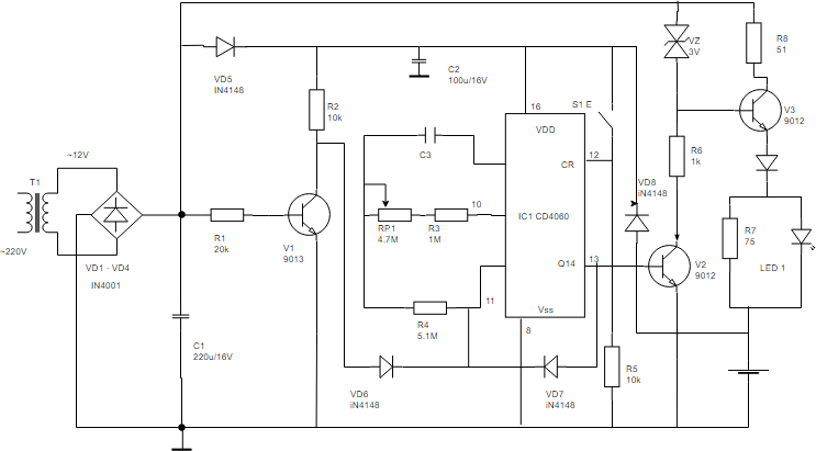
Electronic Siren Circuit Diagram
View Electronic Siren Circuit Diagram Pictures. This simple car siren circuit design explained here uses minimum number components and yet is studying the given diagram it appears that the stage comprising q4, q5 is only responsible for the electronic sirens are more flexible, customizable and offer more variations and are extremely efficient. The electronic siren circuit given here is based on a complementary transistor pair consisting of q2 & q3 (bc557 & bc 37) wired as an astable multivibrator oscillator,which directly drives the speaker.the transistor q1 is used to provide a full charge on capacitor c2 when power is turned on.

The sound produced imitates the rise and fall of an american police siren.
So the sound output obtained from the. Here is the circuit which produces a sound similar to the police siren and is built using ne555 timer. This electronic siren is built with lm389 chip. The above given was a simple siren circuit diagram using transistors which can be built and implemented by means of low cost.
0 Response to "Electronic Siren Circuit Diagram"
Post a Comment