Get Electrical Wiring Diagram Symbols Images. Wiring diagrams use simplified symbols to represent switches, lights, outlets, etc. These electrical and electronic circuit symbols are generally used for drawing schematic diagram.
Electrical Diagrams and Schematics Instrumentation Tools from instrumentationtools.com In situations where there's more than one common electrical symbol, we've. The below given diagram shows a simple method of connecting a socket with a switch. Standard electrical iec symbols also known as iec 60617 (british standard bs 3939) used to represent various devices including pilot lights, relays, timers and switches for usage in electrical schematic diagrams.
In situations where there's more than one common electrical symbol, we've.
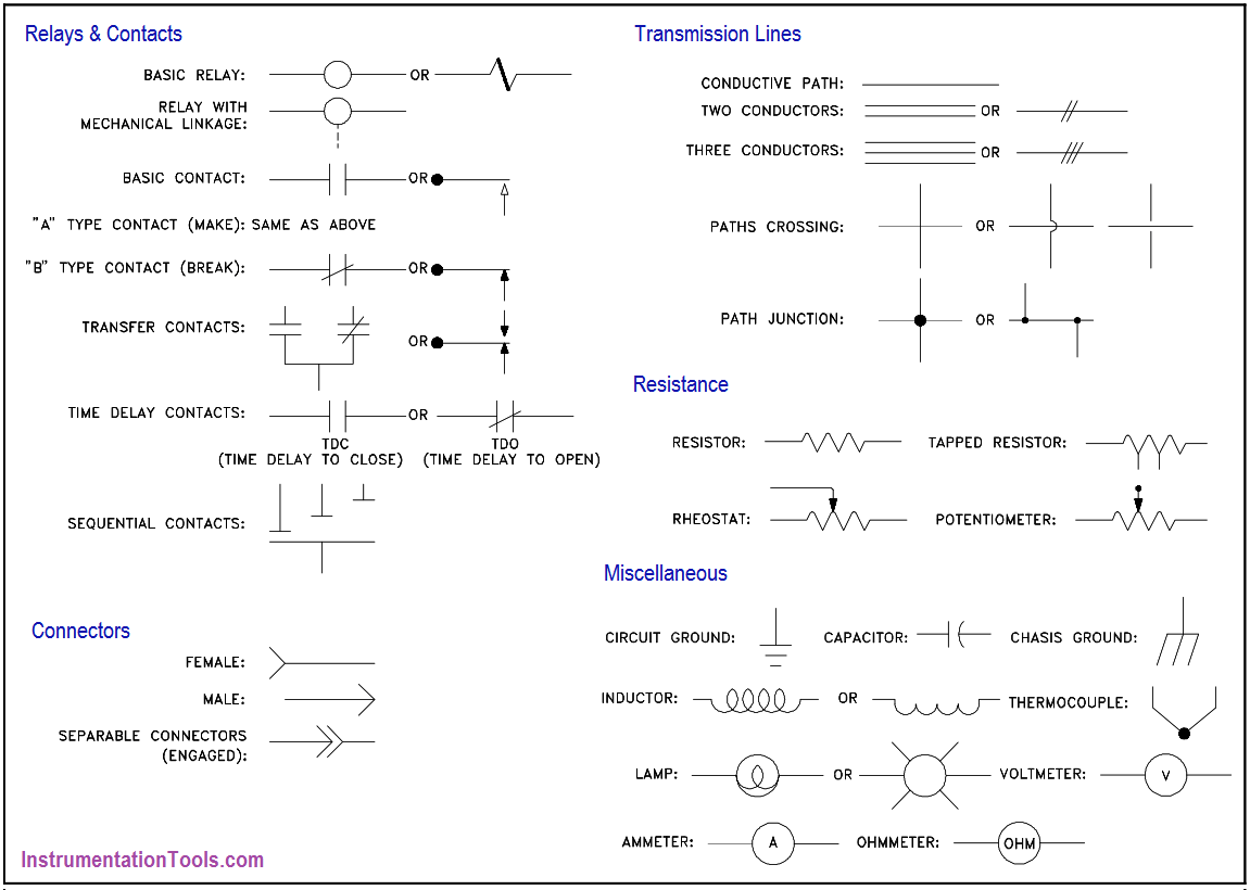
Wiring diagrams use simplified symbols to represent switches, lights, outlets, etc. To read and interpret electrical diagrams and schematics, the basic symbols and conventions used in the drawing must be understood. Traditionally these symbols may vary from country to country, but today they are standardized. Circuit symbols overview resistors capacitors inductors, coils, chokes & transformers diodes distinct symbols have been used to depict the different types of electronic components in circuits, since the very beginning of electrical and electronic science.

0 Response to "Electrical Wiring Diagram Symbols"
Post a Comment