Electrical Wiring Ladder Diagram
37+ Electrical Wiring Ladder Diagram Gif. The ladder diagram is the universal programming language of plc. Bryan covers more electrical basics, 240v circuits, 120v and 24v with the differences between l1, l2, neutral, common and ground for hvac/r and an.
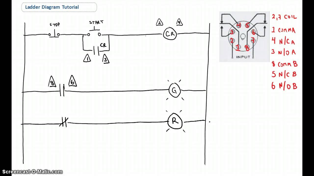
Ladder programming (see chapter 5) has evolved from electrical wiring diagrams for relay control systems, as in figure 1.4, and has the advantage of being readily understood by those familiar with electrical wiring diagrams.
Ladder diagrams are composed of two vertical power rails and horizontal logic rungs to form what the first difference is the control logic in an electrical schematic is represented using components the rungs in a ladder diagram represent the wires that connect the components of a relay control. A contact has only two states: When wiring up the inputs and outputs to the plc, the relevant ones must be connected to the input and output terminals with these addresses. Fast and easy ladder diagrams draw ladder diagrams much faster and easier than with most cad software.

0 Response to "Electrical Wiring Ladder Diagram"
Post a Comment